User Interface Tour
The Design Studio UI, shown below, consists of a Design Canvas with a grid background in the center flanked on left and right hand side by the Models & Solutions Catalog Palette and the Properties & Matching Model Palette. At the bottom of the Design Canvas is the Validation Console. At the top are the New, Clear, Validate, and Save buttons.
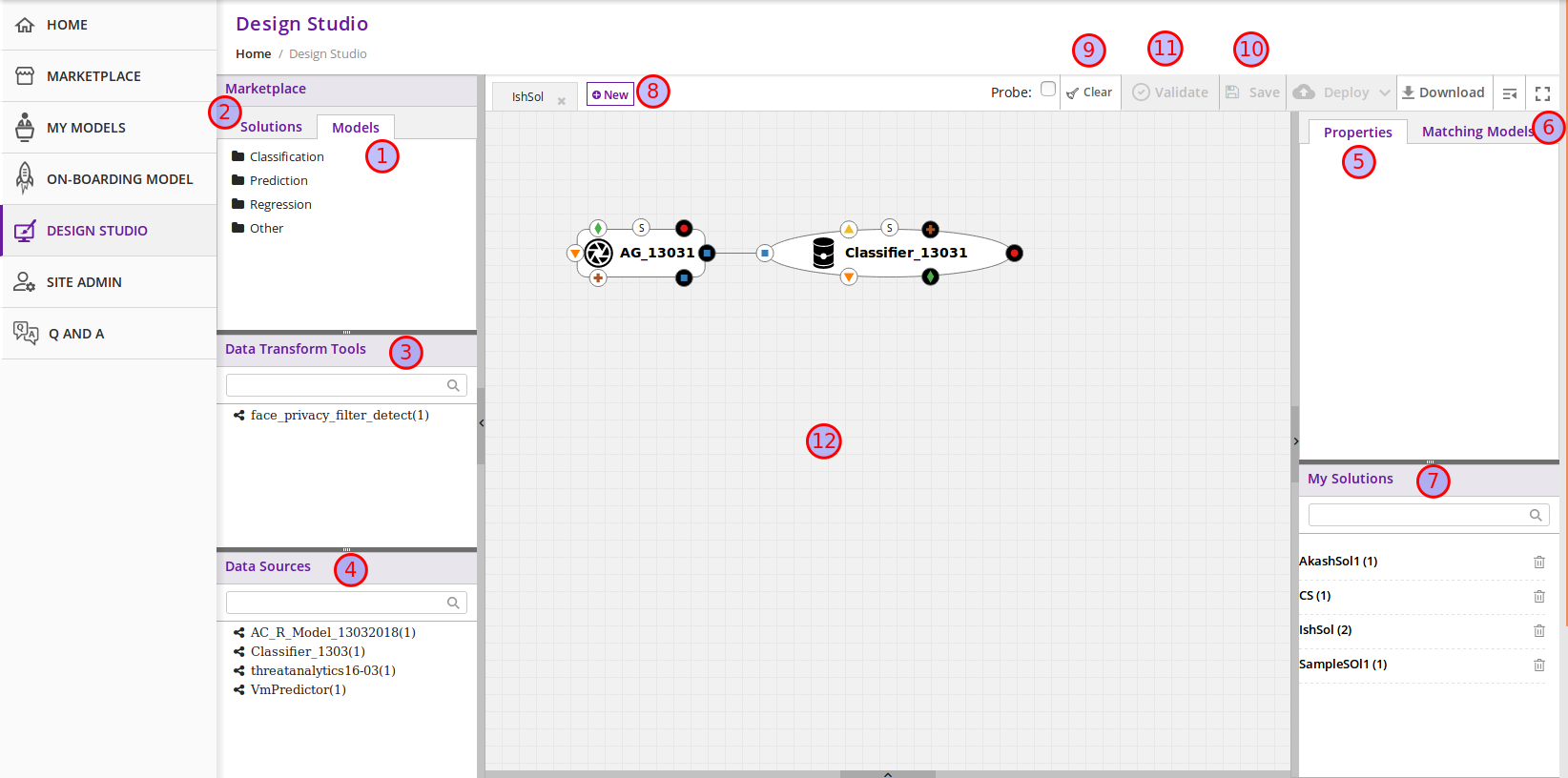
- Models Tab: Displays the catalog of the ML Models – the basic building blocks used for creating composite solutions. The models are currently classified under four categories – Classification, Prediction, Regression and Others
- Solutions Tab: Displays the catalog of composite solutions (built out of basic building blocks) that have either “Public” visibility or belong to the logged in persons “Organization”
- Data Transformation Tools: A set of useful data transformation utilities are displayed here. Currently there is a Data Mapper which performs mapping between some basic Protobuf data types, such as int32, string, float, double and bool. An Aggregator is another utility that is planned to be deployed there.
- Data Sources: This section is meant to represent data sources which feed the ML Models. It could be any entity that produces data that is consumed by ML Models and Data Transformation Tools, such Data Lakes, Databases, Cell Towers, Network elements which produce data such as Routers, Switches, etc.
- Properties Tab: Displays the properties of elements – such as ML Models and Messages inside the Ports. If an ML Model is selected by the user in the Design Canvas, it displays the name, type, owner, provider and tool kit type information. If a Message inside the ML port is selected by the user, it displays the Protobuf message signature – such as the fields of the message, their name, type, tag and role (repeated, optional etc.)
- Matching Models Tab: If a requirement (output) port of an ML Model is selected in the Design Canvas, then this tab shows a list of all models that have matching capabilities (in their input ports). The user can then drag the desired model in the Design Canvas and connect the output port to the input port. If a capability (input) port of an ML Model is selected in the Design Canvas, then this tab shows a list of all models that have matching requirements (in their output ports).
- My Solutions: Displays the catalog of composite solutions (built out of basic building blocks) that are marked “Private” to the logged in user. When the user clicks on an existing solution, that solution is displayed in the Design Canvas. The user can then make modification to the solution and save it as a separate solution by providing a new name or new version or both.
- New: The user clicks this button to create a new composite solution.
- Clear: The user clicks this button to clear an unsaved solution.
- Save: The user clicks this button to save a new composite solution or save changes to an existing solution. The user is prompted to provide the name, version and a description of the solution. The user can make modification to the solution and save it as a separate solution by providing a new name or new version or both.
- Validate: The user clicks this button to validate a composite solution created in the Design Canvas. Both the success and error messages are displayed in the Validation Console. If the solution is valid then a Blueprint.json file is created which is used to deploy the solution in the target cloud.
- Design Canvas: This is where the users drags one or more ML Models – the basic building blocks to create a composite solution or if the user clicks on an existing solution in Solutions or My Solutions tab, it is displayed in the Design Canvas.
Ports of the Model
A model may have multiple ports. A Requirement (output) port is represented by a filled-in circle and a Capability (input) port is represented by an empty circle. The matching pair of ports are represented by identical icons inside their ports, such as diamonds, rectangles, triangles, + sign, etc.
Composition Based on Port Matching
The Design Canvas is the place where the user performs model composition based on the port matching criterion discussed earlier. The Design Canvas ensure that only matching ports are connected via a link. It does not allow non matching ports to be connected, thereby facilitating the design – time validation of the composite solution.
How to name the ML Model
A model name is automatically generated when a model is dragged from the “Models” catalog palette into the Design Canvas. The user can change the name by double clicking on the existing name and overwriting on it.
How to name the Link
Double click on the link – a text box appears, type the name of the link.
On Click of the Model
The model properties such as its name, owner, company, toolkit (Scikit, TensorFlow, R, etc.) are displayed in the Property box.
On Click of the Link
The link properties such as its name appears in the Property box.
On Hover over a Port
The name of the operation and name of either the input or the output message, depending on the port type, pops up in Design Canvas.
On Click of the Port
If the user clicks on an Output (Requirement) port, then all ML Models that have the matching input (Capability) ports are displayed in the Matching Models tab. If the user clicks on an Input (Capability) port, then all ML Models that have the matching Output (Requirement) ports are displayed in the Matching Models tab
On Click of the Message
When the user does a mouse click on a port, then operation and message name(s) pop up. Now the user can click on the message and Protobuf message signature appears in the Property tab.
Validation Console
When the user requests the validation of the composite solution, the Validation Console pops up from the bottom of the Design Canvas. This is where all the success and error messages related to the validation gets displayed.